The wide field and atmospheric dispersion corrector (WFC/ADC) corrects for image
aberrations. The system consists of 4 lenses with 2 counter-rotating prisms.
The WFC creates a nearly unvignetted image of 2.6 degrees diameter in the focal
surface of the telescope. The ADC corrects for atmospheric dispersion up to 55
degrees zenith distance and hence at larger zenith angles has poorer performance
as object light gets dispersed in the focal surface and light at the end of the
4MOST wavelength range may miss the fibre. In simulations, the WFC has a quite
homogeneous throughput over the whole field averaging to 84.6%. The plate scale
of the WFC is about 59.4 μm/arcsec.
Acquisition & Guiding and Wavefront Sensor System
Two A&G cameras will be implemented for redundancy and in order to increase the
sky coverage, but only one of them will be active at any time. There are four
WFS cameras around the edge of the field of view. Each WFS camera
(2048x2048, 13.5 μm pixels) samples a 27.6 mm × 27.6 mm patch of the field,
equivalent to about 7.75' × 7.75' (60 arcmin2).
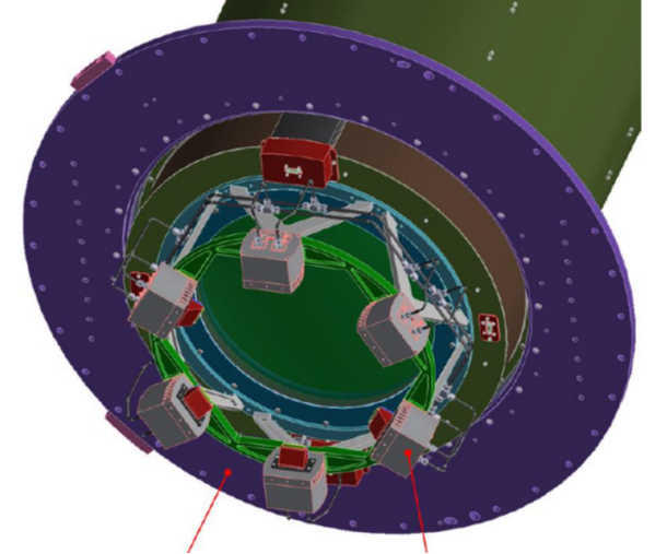
Fibre Positioner
AESOP prototype with 64 spines, showing the fibre positioner in action.
Credit: Scott Smedley
The AESOP fibre positioning system is based on the tilting spine principle. It
can simultaneously position all the 2436 science fibres that are arranged in a
hexagonally shaped grid at the focal surface within 2 minutes. This includes not
only the time required by the fibre positioner to move the spines, but also the
time required by the metrology system to locate the fibres within the field of
view and provide the Fibre Positioner with the position information necessary to
reach the target. The accuracy of fibre positioning is expected to be better
than 0.2 arcsec, thanks to the 4-camera metrology system. The tilting spine
positioner has the advantage that each fibre has a large patrol area. The pitch
between spine tips is 9.542 mm (~161 arcsec) and each spine has a patrol radius
of at least 11.8 mm (~200 arcsec). The closest separation that can be achieved
between fibres is expected to be about 15 arcsec on any side. Each target in
the science field of view can be reached by at least 3 fibres that go to one of
the Low-Resolution Spectrographs and one or two fibres that go to the
High-Resolution Spectrograph. This ensures a high allocation efficiency of the
fibres to targets, even when targets are clustered.
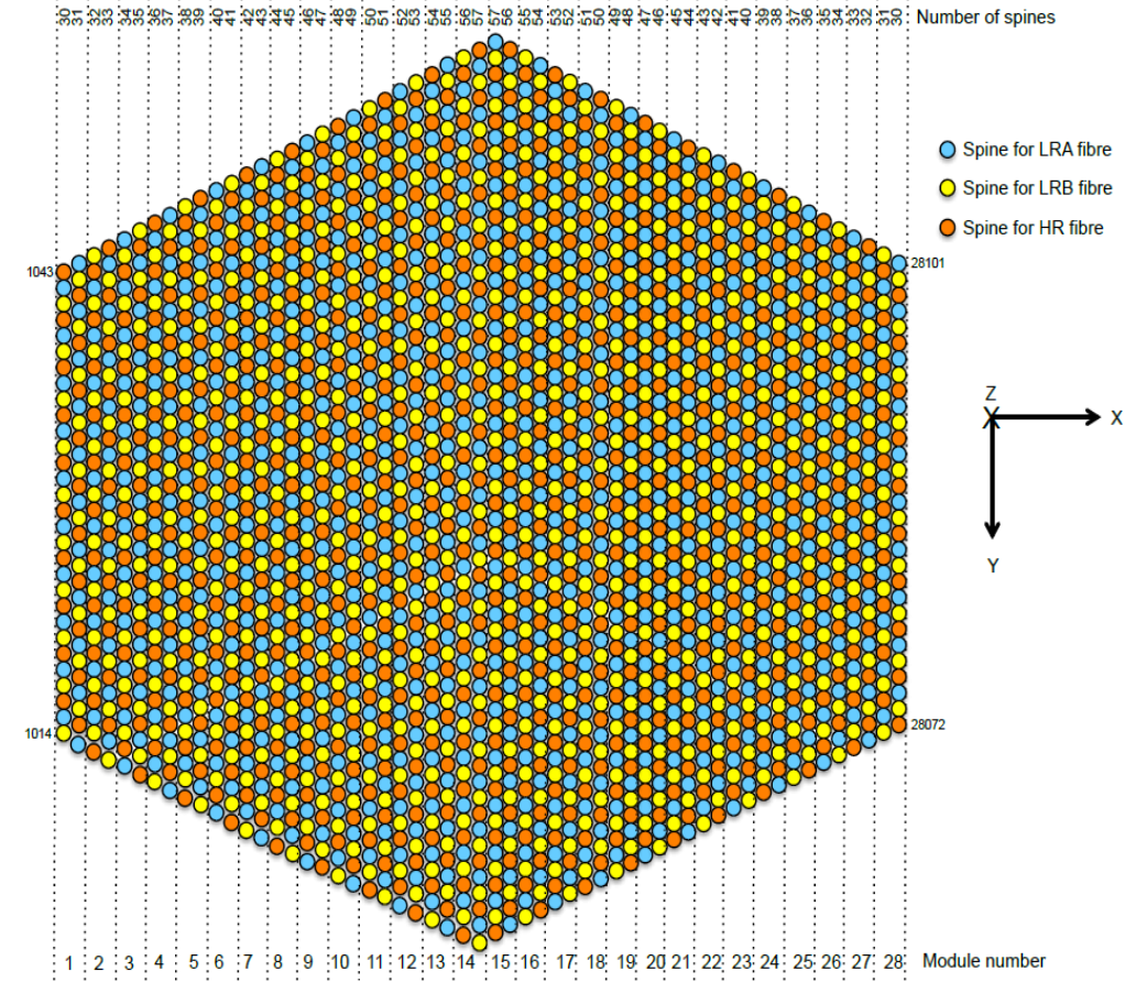
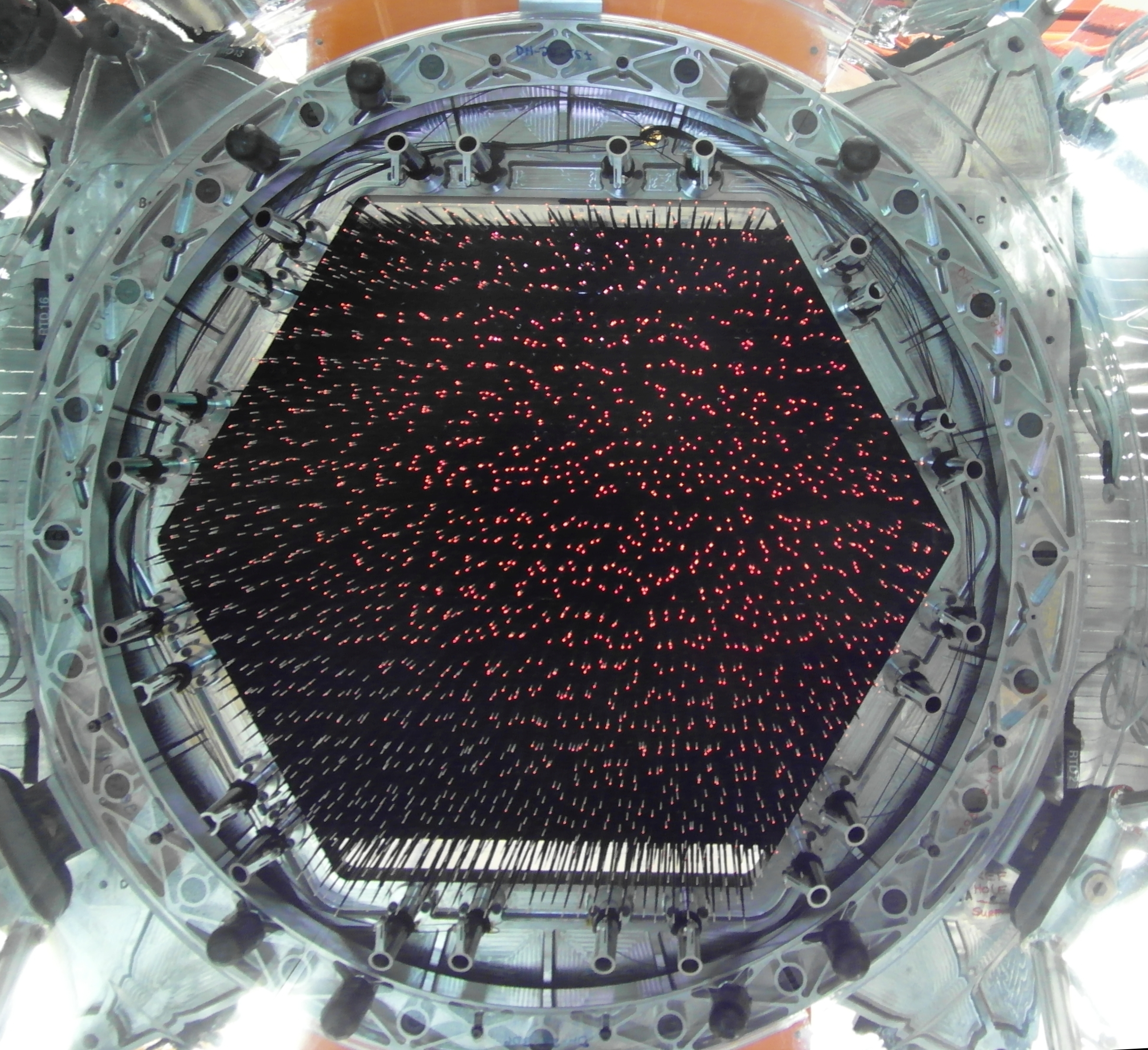
Left: arrangement of the 2436 science fibres in the focal surface and their
mapping to the three spectrographs. In each column of spines, the
fibres alternately feed LRS-A, LRS-B and HRS (as indicated by the colour code).
All fibres are physically identical, i.e. all have the same core and cladding
size. Right: the 4MOST AESOP fibre positioner with all the fibres in the spines
back-illuminated with red light, allowing the metrology system to identify their
position.
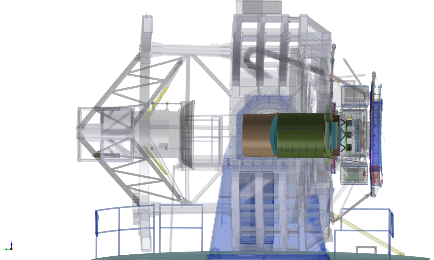
Fibre-Feed System
The Fibre-Feed System is situated between the Cassegrain focus of the telescope
and the spectrographs. It facilitates the transmission of the light
from the science targets imaged at the focal surface to the slits of the
spectrographs. In total, the system connects the 2436 science fibres to one
high-resolution specrograph and two low-resolution spectrographs, featuring
812 fibres each. In addition, 36 calibration fibres feed calibration light into
the three spectrograph slits. 12 guide bundles and 24 fiducial fibres complete
the main fibre system. Additional fibre links provide the connection from an
LED light source to back-illuminate the science, guide and fiducial fibres.
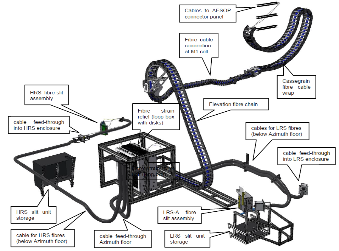
View of the fibre feed routing without showing the telescope, the fibre
positioner or any mechanics. The cable chains contain the science, guide and
fiducial fibres. After the loop boxes the conduits connect the science fibres
to the three spectrographs. An additional cable carries stationary calibration
and back-illumination fibres from the azimuth floor cabinet to the three
spectrograph slits.
Metrology Cameras
The Metrology System measures the location of all fibres in the focal plane and
translates it to the targets on sky. The main components are a set of
4 identical cameras, imaging the whole field-of-view; and a back-illumination
unit that illuminates all science and fiducial fibres, as well as the central
fibres of the secondary guide bundles.
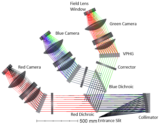
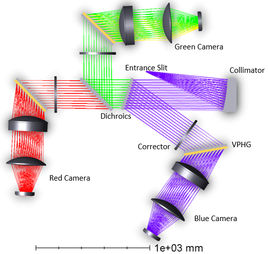
Spectrographs
Two identical low-resolution spectrographs (LRS, left) and one high-resolution
spectrograph (HRS, right), fed by 812 fibres each, provide simultaneous
measurements of 2436 spectra. Each spectrograph has a blue, green, and red arm,
in fixed configuration, and each arm is equipped with a 6k × 6k CCD detector.
The LRS provide continuous wavelength coverage from 390 to 950 nm at a
resolution of R > 4000. The HRS covers the ranges 392.6 – 435.5, 516 – 573, and
610 – 679 nm at a resolution of R > 18,000.
Detectors and Cryostat
There are nine identical deep depletion detectors for all spectrographs and
arms, with 6144 (H) × 6160 (V) pixels of 15 µm size. The readout noise
is < 2.3 e- (@ 100 kHz).
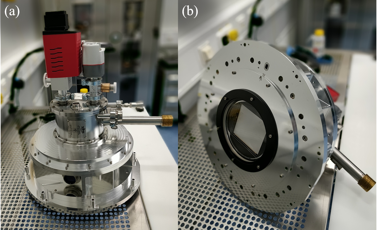
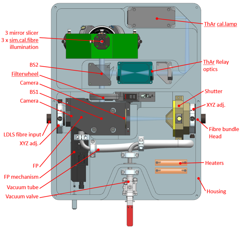
Calibration System
The calibration system uses a Fabry Perot (FP) etalon, illuminated by a Laser
Driven Light Source (LDLS) to provide a regular comb of spectral lines for
wavelength calibration. Additional wavelength calibration can be done with a
ThAr lamp. The FP is in temperature-controlled vacuum and therefore very stable.
The calibration light can be fed both through the telescope plus science fibres
combination as well as directly through the simultaneous calibration fibres into
the spectrograph slit to ensure accurate wavelength calibration. This will
ensure an accuracy on stellar radial velocities better than 1 km/s.